Create an angled shopfront
This documentation describe how to create a shopfront frame with specific angle on top that are not 90 degrees
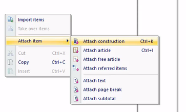
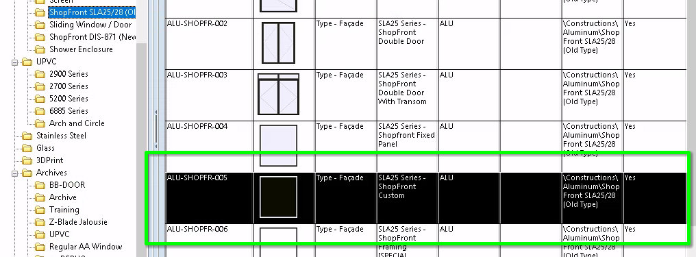
1. Insert a New "Shopfront Custom" in your quotation or order
- Create an order or quotation for the client
- In this order/quotation insert a new item using the construction template "SLA25 Series- Shopfront Custom"
- Click OK to start editing the construction Template
-
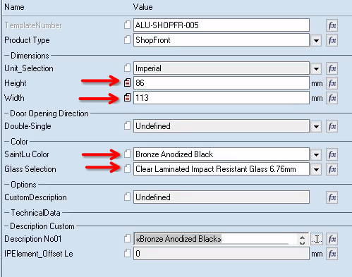
2. Adjust standard dimensions
- Adjust the dimensions, Color and Glass
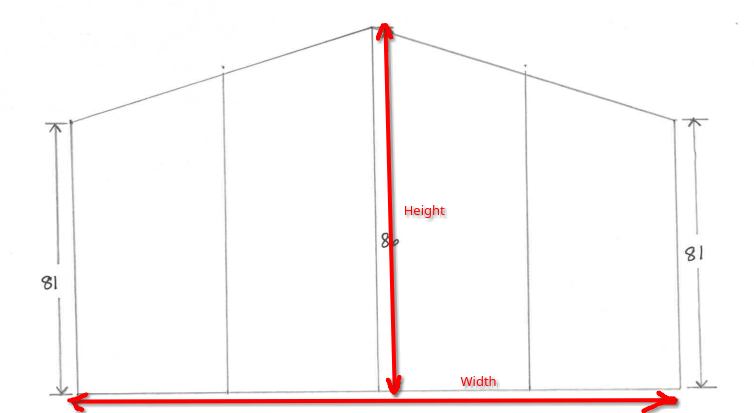
- The height is the taller height of the assembly.
In this example we will use Height: 86” and Width: 113”
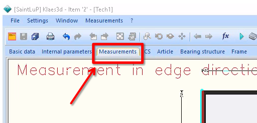
3. Change measurements
- Go to the Measurements tab
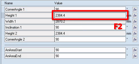
- Click in the field of the Height\~1
- Press F2 to modify the field
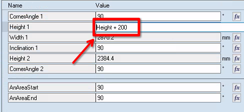
- Change the value from “Height” to “Height+ 200”
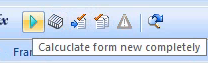
- Click on the green arrow to recalculate the dimensions.
 |
|
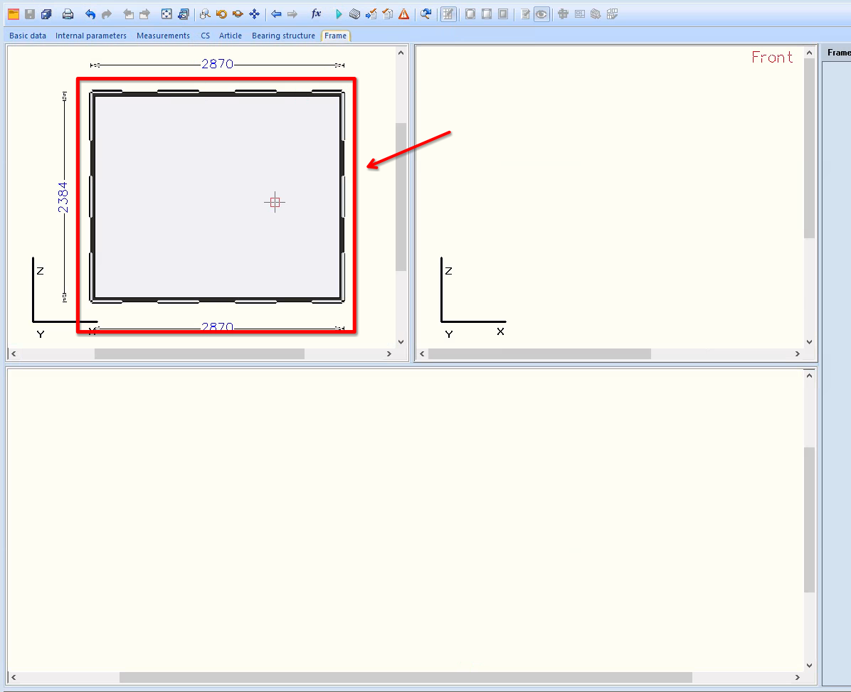
4. Go to the frame tab
- Go the the Frame tab
- Click on the frame on the top left window
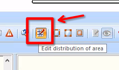
- Select Edit distribution of area
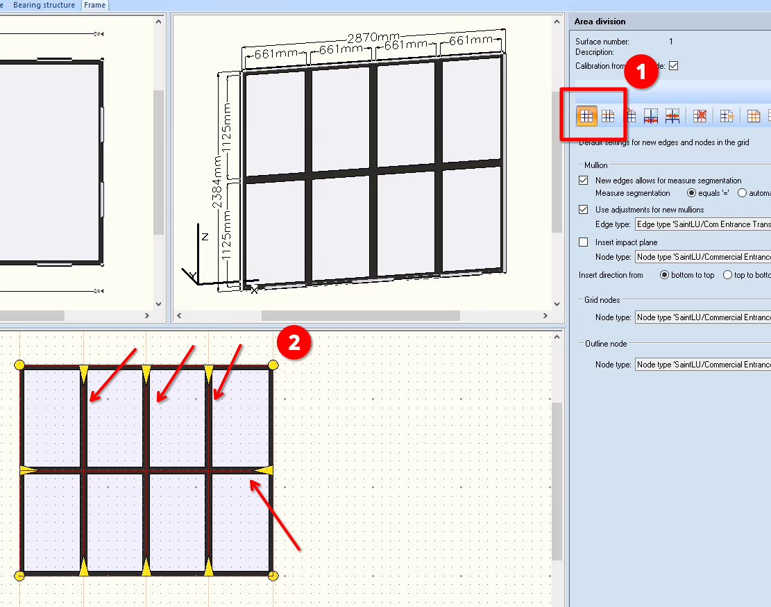
5. Use the Insert New Mullion and the Insert New Transom
- (1) Click on the Insert New Mullion tool to insert vertical separation
- (2) Click on the frame on the bottom window to insert as many mullion as you need
- Repeat with the Insert New Transom tool to insert horizontal separation
⚠️ Add one more transom (Horizontal separation) than necessary, we will need it later in this tutorial ⚠️
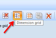
6. Select the dimension to change
- Go to edit Dimension grid
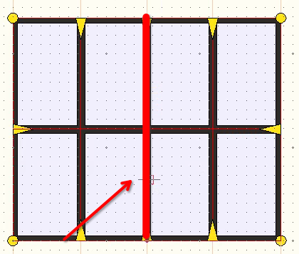
- On the bottom window select the edge in the middle of the frame
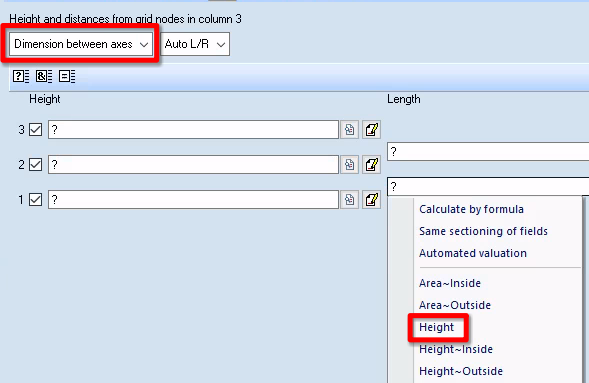
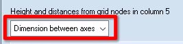
7. Input the new dimensions
- Change the Distance Option to “Dimension between axes”
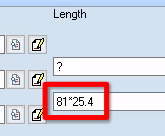
- Select the length at the bottom
- Option A: click on the box, press Shift+F4 to show all the available variables and select the variable Height
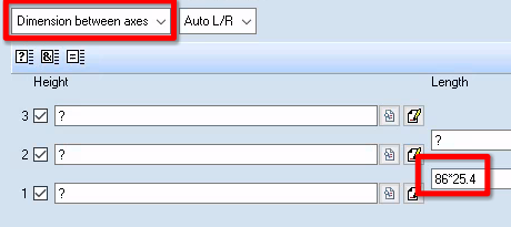
- Option B: Enter the Height of the shopfront in mm. In our case it will be 86*25.4
- Option A: click on the box, press Shift+F4 to show all the available variables and select the variable Height
8. Apply the new dimensions
- Calculate the new dimensions
- This is what the shopfront should looks like now

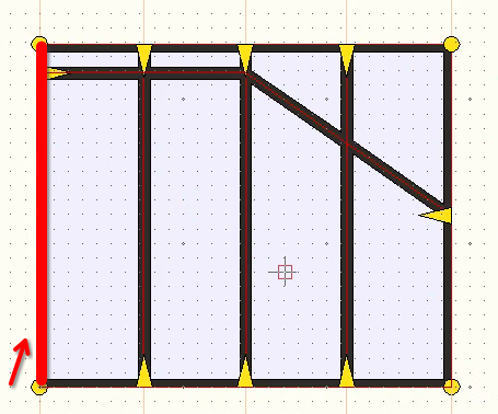
9. Change the dimension of the left side
- Select the left side of the frame.
- Make sure the dimension option is set to “Dimension between axes”
- Change the dimensions of the left side of the frame (in mm).
In our case 81*25.4mm - Calculate the change
- Repeat for the right side
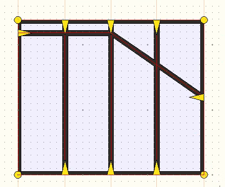
10. Check that everything is correct so far
| ![][image22] |
|---|
- This is what everything should looks like so far
11. Remove the edges on the top
| ![][image23] | ![][image24] |
|---|---|
| ![][image25] | ![][image26] |
- Go to the Edit Edge Type tab
- Select No Edge/Delete Edge
- Go to the Assign Type mode
- Select all the edges that need to be removed and execute
12. Set the top edges to Frame Top
| ![][image27] | ![][image28] |
|---|---|
- Select Frame Top
- Make sure that you are still in Assign Type mode
- Set all the edge at the top to be Frame Top
13. Correct the edge orientation if necessary
| ![][image29] | |
|---|---|
| ![][image30] | ![][image31] |
- Go to Modify Edge Orientation
- This will show the edge direction for all sides.
- Make sure the edges on the outside frame turn anti-clockwise ↺
- If the edge goes in the wrong direction click on it to invert the direction.
Calculate the form
In most cases this should also make the yellow question mark disappear (A yellow question mark means that the glass is not properly aligned on all the edges)
14. Change the Node on top
| ![][image32] | ![][image33] |
|---|---|
| ![][image25] | ![][image34] |
- Go to the Edit Node Type tab
- Select the node type ContinuousVertical
- Make sure that you are still in the Assign type mode
- Apply this node to the top of the triangle
15. Final Check
| ![][image35] | ![][image36] |
|---|
- Calculate the new form
- Select Display Evaluated Construction to see the 3D rendering
- Make sure that there is no gap anywhere.